Electronics
Students should be able to:
- Describe how a semiconductor diode can be use in half wave rectification
- Differentiate between direct current from batteries and rectified alternating current by a consideration of V-t graphs for both cases
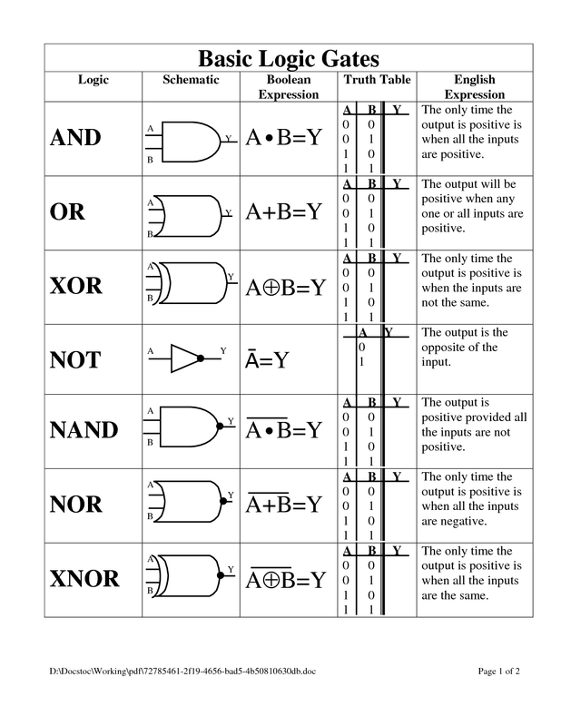
- Recall the symbols for AND, OR, NOT, NAND and NOR logic gates
- State the function of each gate with the aid of truth tables
- Analyze circuits involving the combination of not more than three logic gates.
- Discuss the impact of electronic and technological advances on society
Semiconductors are solids whose electrical conductance lies between that of good conductors and insulators. Germanium (Ge) and silicon (Si) are the best known semiconductor elements.
A semiconductor diode is made by special processes which increase the conductance of semiconductors. Two different types of semiconductors are then joined forming a "junction". At this junction current will flow mostly in one direction.
A semiconductor diode is made by special processes which increase the conductance of semiconductors. Two different types of semiconductors are then joined forming a "junction". At this junction current will flow mostly in one direction.
Rectification
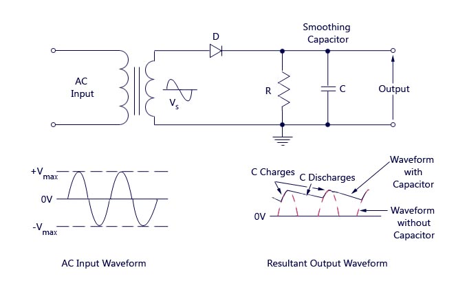
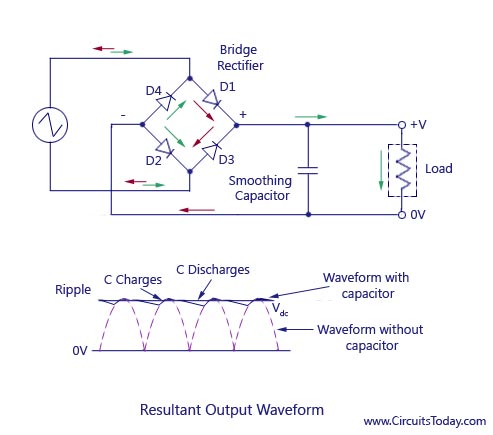
Semiconductor diodes are used to rectify i.e. to convert alternating current to direct current.
A rectifier in an a.c. circuit cuts off the negative half- cycles of the current.
The diagrams below illustrate:
A rectifier in an a.c. circuit cuts off the negative half- cycles of the current.
The diagrams below illustrate:
- Half- Wave rectification using a single diode.
- Full - Wave rectification using a bridge rectifier
Logic Gates
A logic gate is a system of electrical switches which give an output signal that depends on the nature of the input signals.
The signals are small voltages which the gate recognizes in only two states: High (logic 1) and Low (logic 0).
Logic 1 is equivalent to a mechanical switch being ON and logic 0 is equivalent to the mechanical switch being OFF.
A truth table shows the input for various combinations of inputs to a logic gate. There are five (5) basic logic gates. Their symbols and corresponding truth tables are shown:
NOTE: Other logic gates and switching devices used in electrical circuits can be built using combinations of the basic gates. These include light and temperature sensors, alarm circuits and the switching circuits used in traffic lights.
